Small Chinese Hobby CNC Routing Machines
richard.senior@gmail.com 2020 (version 1)Recently the market has seen a lot of new small CNC routing machines introduced. These machines are generally made of modular aluminium extrusions bolted together with steel cap head allen bolts and braced with small extruded brackets etc.
The Axes are driven by stepper motors that rotate small diameter square cut lead screws. The axes are generally supported by two small diameter rods that run through cheap linear ball bearings. A lot of these machines share parts (extrusions, steppers, bearings etc.) with openbuilds machines
These machines are generally named according to their size. For example the CNC 3018 is a machine having a 30cm x axis and an 18cm y axis. Available also are smaller machines such as the CNC1208 (12cm x 8cm) and larger machines such as the cnc6040 etc. These vary wildly in quality and useability depending upon the manufacturer etc.
CNC 3018 Pro
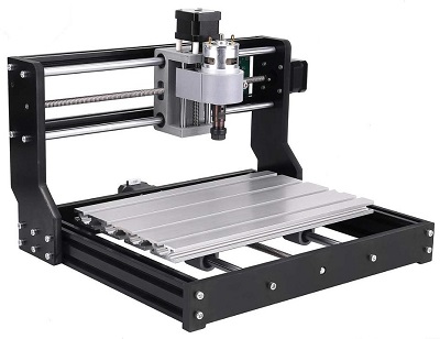
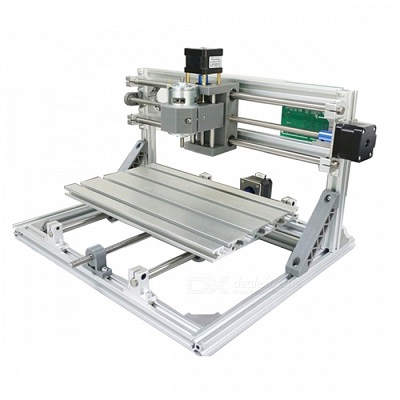
Note the major difference here is the way that the x axis gantry is supported. The Pro uses single piece Bakelite (very hard plastic) pieces, and the basic 3018 uses small brackets.
I was initially disappointed that the supporting brackets were bakealite and not aluminium (the photograph above seems to show all the black parts being made of the same material, anodised aluminium) but in fact the bakelite is more than suitable and actually feels quite satisfying in the hand.
I don’t own a standard 3018, but I am told that the PRO is an improvement in terms of stability, and it’s not much more expensive. Certainly the pro is FAR easier to assemble than the 3018. My engineering sensibilities rather agree with the 3018 pro’s design. It is almost ruthelessly efficient, and incredibly well considered. Anywhere cost can be legitimately saved, it is. In all but one case (I’ll cover below) these cost savings have no impact on the operation of the machine.
The Z axis is largely made from a softish plastic, I’m guessing at HDPE. This is the only part of the machine that feels under-designed. But this is also pretty much where all the cost saving is, so you have to decide what you want. Do you want a CNC router for the cost of a cheap pistol drill, or do you want to spend more, and get more.
Functionality out of the box
Later I’ll be telling you that the CNC3018 pro WILL diamond drag engrave glass and even steel with beautiful results. It will also (with a diamond drag engraving bit) cut vinyl stickers. And it will intricately engrave hard wood and softer metals with the correct rotary engraving/routing tools and preparation.
But out of the box the CNC 3018 pro suffers from vibration and z-axis stability problems that make your initial results sub-optimal. You will be both amazed and disappointed in equal measure depending on your inteded use of the machine. These machines are staggeringly accurate to fractions of a millimetre. They are also powerful enough to run a 5x2mm cut in relatively hard wood at 8mm/s or so. Initially your results (on aluminium) will look like this :
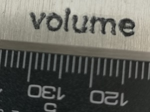
You can see here that although the lettering of the word ‘volume’ is small and accurate, the letter outlines are slightly fuzzy. This is because of tiny vibrations in the machine which I’ll discuss later.
If you’re entirely new to these machines then like me, you’ll wonder what kind of engraving tools the machine comes with? The standard collet is a chinese style “ER11″. The collet you’ll get will likely be for 1/8th” tools, which are the type that fit in the dremel multitool collet. Shown here is a typical ‘standard’ 1/8th inch engraving tool.. you usually get about 10 of them initially :
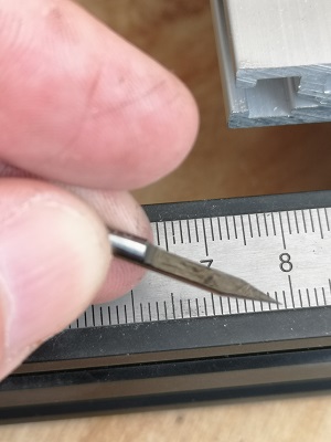
The word ‘volume’ in the above picture was cut with one of these tools, and I later filled the engraving with paint. From a distance this looks fine.. but up close it seems cheap.
If you’ve bought one of these machines (or are thinking about it) the chances are you’re pretty handy. You’re probably an engineer of some sort, and have access to other tools and knowledge to use them. When you buy one of these machines your mind will INSTANTLY start bombarding you with ways you can improve it. You’ll spend a few hours making T-Nuts for instance (though you can buy them cheap enough (google for Bosch Rexroth Strut Profile T-Slot Nut).
You’ll spend a while browsing the internet for other people who own these machines, and find all sorts of talk on forums (probably how you found this).
And lots of people have a lot to say. But I think I can give you difinitive advice after many weeks of experimentation.
So here is my advice :
Essential modifications
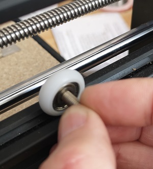
Oilite z-axis leadscrew bush (cost: 1/2 pint of beer. time: instant)
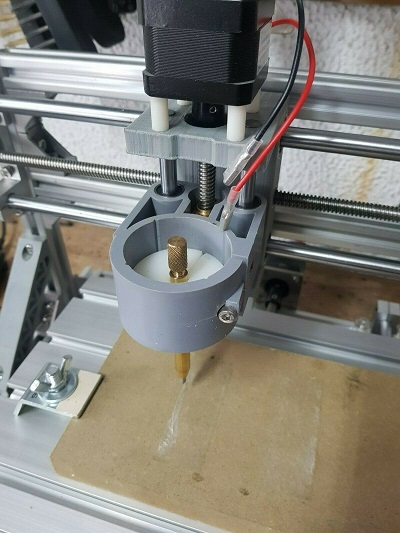
The first thing you will absolutely want to do is fit an oilite bush in at the bottom of the z-axis lead screw if it isn’t there already.
A lot of the cheaper 3018 pro kits are missing this bush, even though the z axis is cut to recieve one :
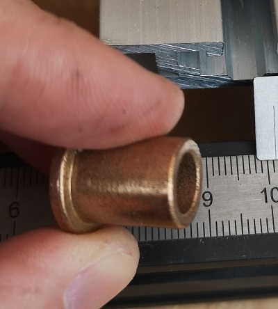
This bush came from an ebay seller so it’s unlikely this link will work at your time of viewing this. But the dimensions of the bush are: 8mm bore, 16mm long, 12mm od with a flange.
This bush will literally push in by hand from the bottom of the z-axis without any disassembly, and it will fix around 50% of ALL vibration and deflection instantly. For a cost of half a pint of beer. Why the 3018 doesn’t come with this already fitted is a mystery. Perhaps they’re hard to source in China?
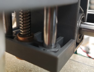
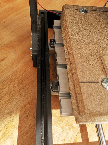
Others online also recommend replacing the linear bearings in the z-axis with longer ones. However, this will severely reduce the operating range of the z-axis :
It will also make only a small difference in reducting overall tool deflection, because bigger problems exist with things like x-axis torsion etc. And worst of all it requires you to entirely disassemble the z-axis, which is time consuming.
I bought some of these longer bearings but after fitting the oilite bush right at the start and realising it cured most of the deflection attributable to the z=axis itself, I decided I would rather compromise and retain the 15mm or so z-axis range.
However I’m now at the stage of chasing the last tiny bit of z-axis movement and I’m reconsidereing fitting the longer bearings. Or maybe I might just construct a new strong z-axis myself and use the longer bearings in that, and increase the z-axis range at the same time.
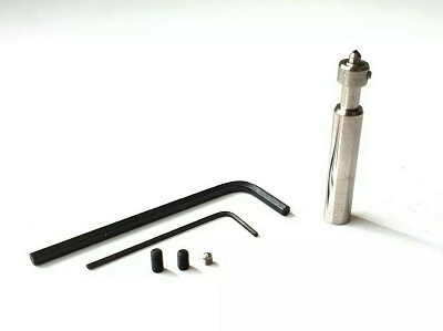
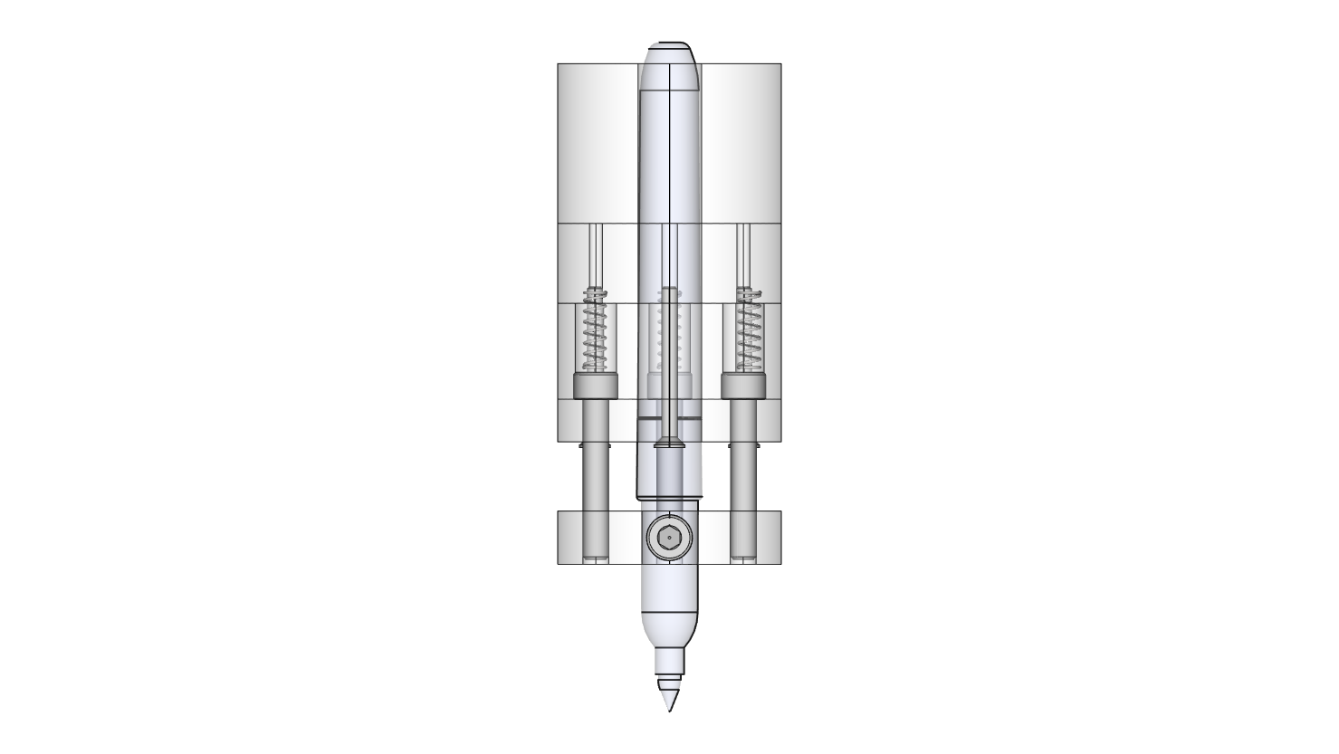
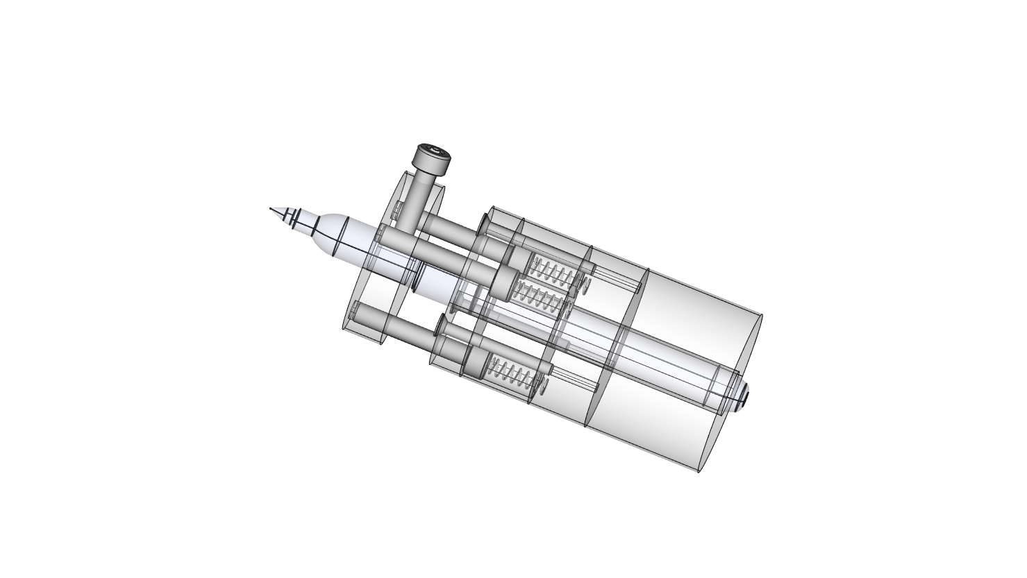
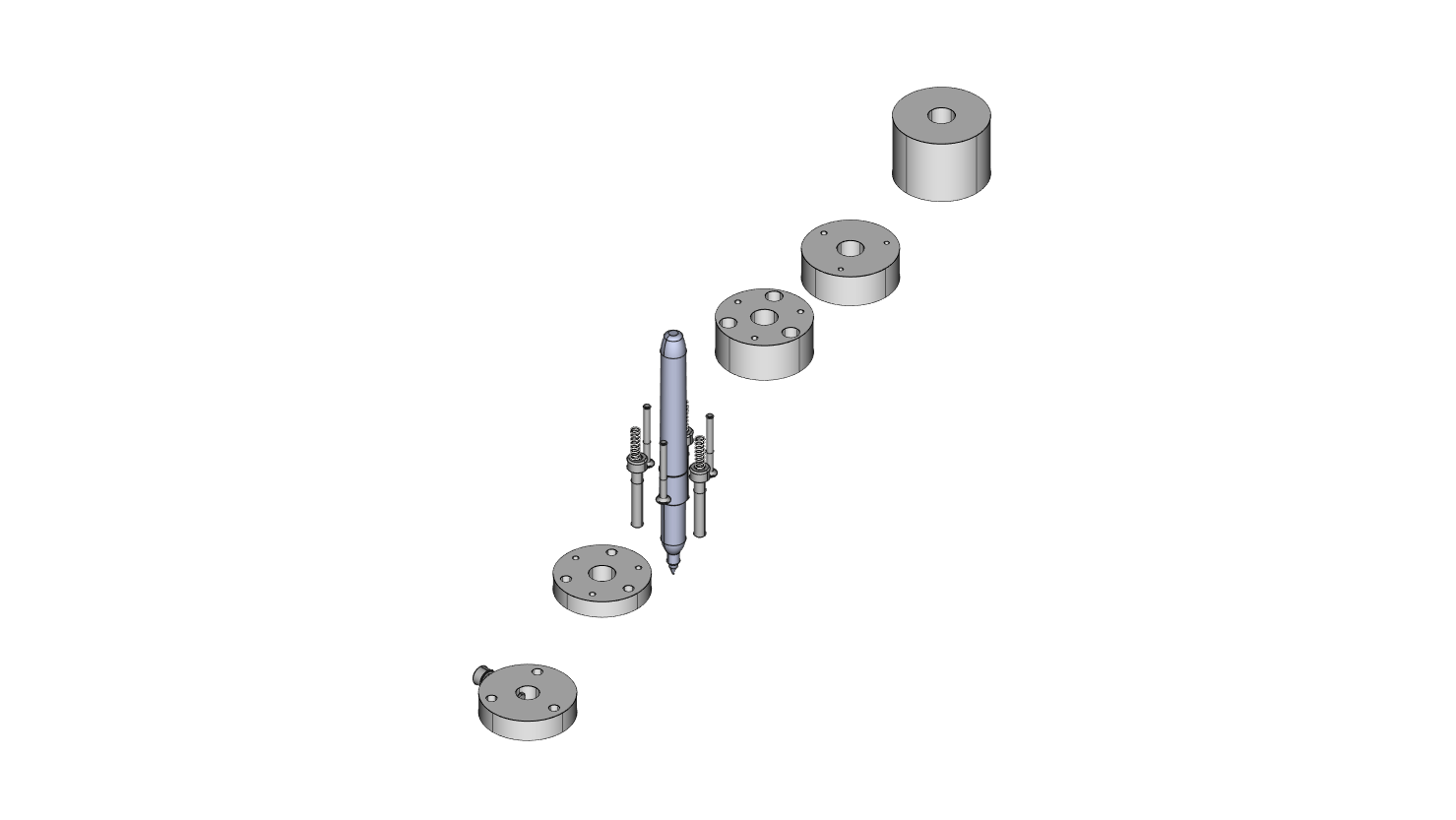
The sprung diamond drag cutter
I think this tool is the secret missing sauce of cnc professional high quality engraving.
The name says it all really. This is a diamond tipped engraving tool which is spring mounted such that it applies a constant pressure on the job no matter if the depth of the job varies slightly. This tool is dragged across the job like a scribing tool and does not rotate (Must not rotate in fact) like a cutter or burr. So we generally replace the whole spindle with the drag tool and a purpose made holder.
You will initially try drag engraving with a standard router knife bit in a spindle that is not rotating. But even tiny discrepencies in the machine bed height or your job itself will cause problems with setting the z-axis depth correctly. You’ll snap the very tip off the ends of a few tools too, and ultimately get disapointing shallow scratches.
Using a sprung diamond drag tool turns the 3018 into a genuine tool. The diamond is sharp enought to precicely cut vinyl and also to leave a solid mark on glass ceramics or even hard steel. And the spring means that you don’t have to worry about z-axis depth problems.
Including the diamond dip, and the spring housing etc. these cost around 40 quid a pop. You might feel reluctant to shell out almost a third of the cost of the whole cnc 3018 on a simple tool. But in honesty if you intend to engrave with the 3018, the sprung diamond drag tool is mandatory.
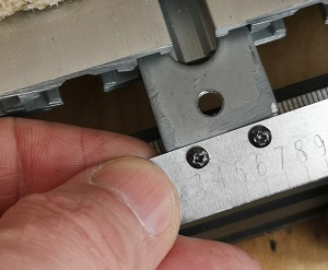
See below (vernier plates) for examples of engraving hard shim steel with the diamond drag tool.
Recommended modifications
PTFE rail support shims (cost: 2 pints of beer. time: a few hours>
Ok but what about the other 50% of the vibration that is not fixed by the oilite bush?
This is a can of worms and is really due to the fact that the CNC3018 pro is not a ‘serious’ tool. You’re really starting to fight with the difference between
spending 100 and 1000. The remaining vibration has no single cause, but is inherent in the ‘budget’ design of the device.
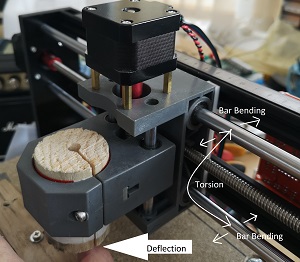
The first thing we notice when we get hold of the cutting tool and try to move it with our hands, is that there is deflection in the x-axis itself :
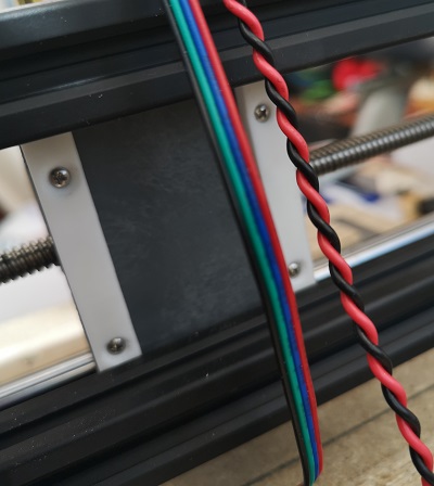
My first attempt to remedy this was to make use of the extruded aluminum bars that hold the rear of the machine together. I screwed some PTFE strips to the rear of the z-axis such that they were very loose push fit against these struts :
I ordered a bit of 5mm thick PTFE from ebay, it cost about 4 quid (about 5 bucks). I cut two 1cm strips with a hacksaw. I drilled and countersunk the PTFE strips with two holes. Remove the z-axis from the x-axis, and screw the ptfe to the back of the z axis using some short self tapping screws. Obviously be careful not to run your screws into either of the linear bearings, or the lead screw!
This is tricky. You don’t want the ptfe to be too thick and cause the x axis to bend. But you also need the PTFE to remain in contact with the beams. I did this by leaving the z axis in situ and sanding and offering up the ptfe runners until they were the right thickness. Then and only then I removed the z-axis and screwwed on the strips. bear in mind that the extruded bars screw into the rest of the chassis, and so there is a tiny bit of play to be had in the screws if you get it wrong by a few thou etc.
I do recommend you do this, it does work.
You could use nylon or really any reasonably hard plastic but PTFE is the right choice for this application because of its low friction.
I did at first consider canibalising an old ikea style white plastic kitchen chopping board. I think they’re made from polythene, but they might
work at a push if you can’t get any nylon, ptfe, or HDPE etc.
In my mind this should have fixed most of the remaining vibration/deflection problems. But there is a curious levering effect. If we pull the chuck hard towards the front of the machine we push the top of the ptfe runners against the top extruded bar (which we intended obviously). But that effectively levers out the bottom of the z-axis. How to stop the levering effect?
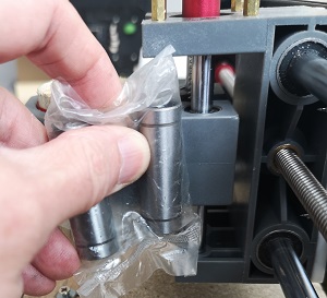
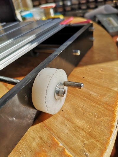
Openbuilds style rail rollers (cost : a few pints of beer. time: 4-5 hours, use of a lathe, and a LOT of swearing)
At this point I remembered that the extruded rear rails are actually ‘openbuilds’ rail, and as such I knew I could buy delrin runner wheels which would fit into the grooves. Perhaps I could fit two wheels to the rear of the z-axis which would run in the gooves and completely prevent deflection in the x-axis rail bars? :
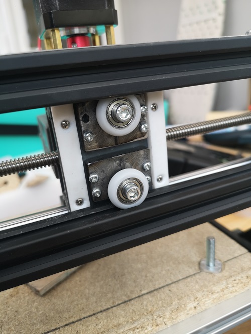
I realised immediately that this would be a lot of work. Getting both wheels to be in contact permanently, but not distorting the bars. Mounting the wheels securely on the plastic z-axis. etc. As you can see they fit neatly behind the z-axis and do effectively prevent tortion in the x-=axis.
Was it worth the effort, did it make enough of a difference to warrent the 4 or 5 hours or so spent fitting them? I think I’m 50/50 on that. I will say this though. Now that they’re on and fitted I’m happy they’re on and fitted.
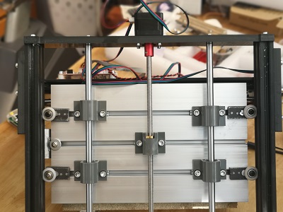
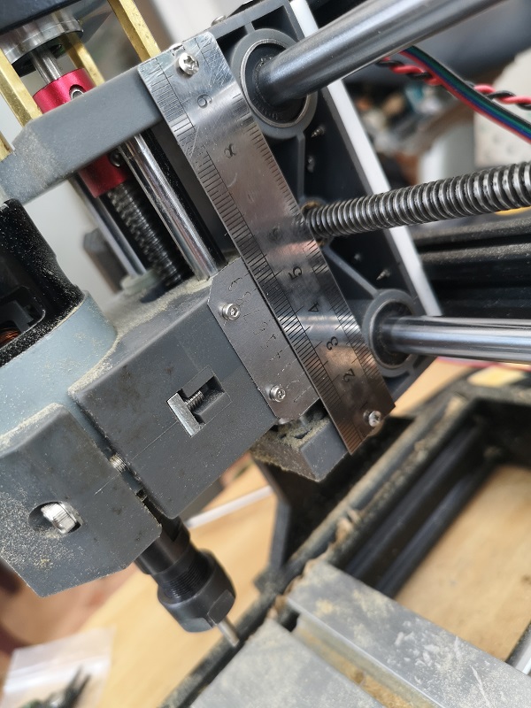
Combined with the ptfe runners you can absolutely remove any z-axis deflection attributable to torsion in the x-axis. In fact decided to also do this on the y axis :
Optional but very useful modifications
Analogue DRO’s (yes I know that’s an oxymoron, and a misuse of the word ‘analogue’)
cost, a couple of pints of beer. time: a couple of hours.You can buy Digital Read-outs that will fit on the CNC 3018.
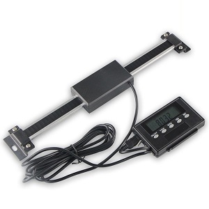
You can also canibalise cheap digital vernier calipers to make your own DRO’s. And I seriously considered doing this.
The problem with using a cheap vernier caliper as a DRO is that the vernier may get re-zeroed. Using the zero reset on a vernier caliper DRO may actually be very useful, but it does mean that your DRO will not be ‘Absolute’. From one job to the next you will either have to go through some process of unmounting and re-zeroing the capiper, or rely on the very course markings on the vernier itself.
It’s also not as cheap as you might think. The cheapest digital vernier I ever found was sold by ALDI in the UK at a cost of 7 quid (sort of 10 bucks). Then there’s actually doing the deed. I’m no gardener. I hate killing things of beauty ‘for the greater good’. And I have a soft spot for measuring calipers.
One of the first expensive things I ever bought with my own money was a set of Mitutoyo calipers. They represented a big layout for me as a teenager. Even if I could buy calipers for the price of a coffee, I’d still have a hard time butchering them.
The cheapest digital caliper’s I’ve bought were from Aldi in the UK for 7 quid. And I consider them a prize. I would rather stub my little toe hard than cut them. Once (as apprentice) I got caught using a set of vernier calipers (not mine) as a scribing compass, I can still see my mentor’s face.
The cheapest I can find them online now is around 10 quid, and that cost begins to mount, one for each axis. Then there is the actual work. Butchering the calipers is not a simple task, the chances are you’ll destroy at least one of them completely. Unsatisfactory is what it is. Most unsatisfactory.
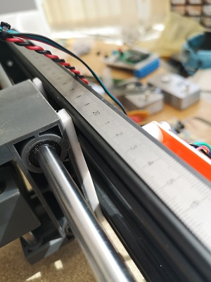
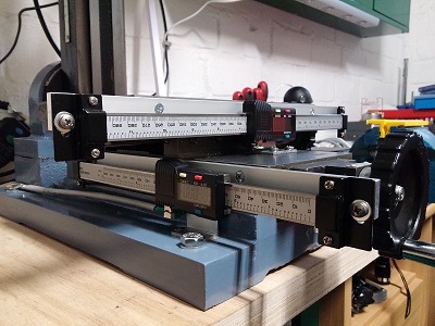
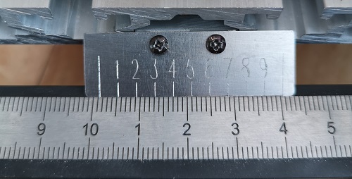
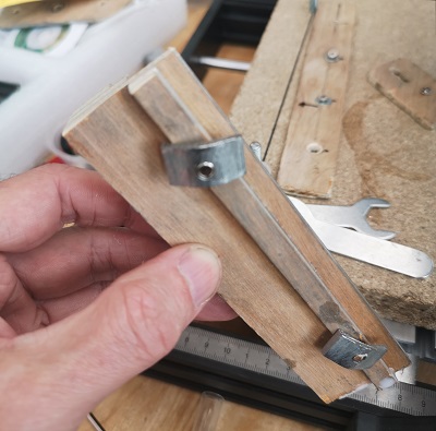
So I had the idea of simply making my own verniers from a rule and a bit of engraved shim steel (see below about engraving steel with a sprung diamond drag cutter):
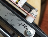
I found a guy on ebay who was selling these 12″ ‘kinex’ rules and got three for 10 quid (12 bucks or so) including postage. I’d never heard of Kinex before. I think they’re from Czechia (which is strangely where I got my 3018 pro from). They’re clear and uncluttered. Metric only, and actually quite high quality considering the staggeringly low price.
It took a while to work out how to engrave the vernier plate but a good clue is to look at a normal vernier caliper and use the same dimensions. Then there’s ‘calibration’ of your CNC router. It may differ from reality just enough that the vernier does’t really work. So your first attempt might need stretching or shrinking until it does work. A good idea here is to mount a pen on the z-axis and just test it out a bit first.
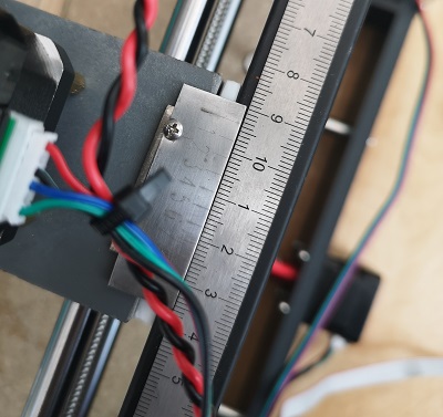
In the picture above the camera actually fish-eyes the photo slightly so the vernier doesn’t look as accurate as it is in reality. But you can see it works, it says somewhere around (juuuust less than) 101.5mm And that is absolute. If the y-axis of the machine is in that position it will always read that position. There is a small issue reading the verner when the y-axis travels behind the Bakelite mounting plate, but it’s not insurmountable. You can still read the position it’s just a little awkward.
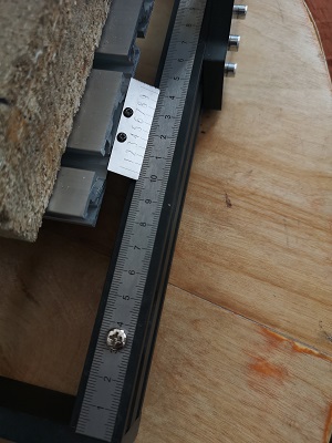
Drilling the rules in the rules to mount them on t-nuts did feel a little sacreligious but once it was done I was quite pleased with the results. Absolute axis measurement to a tenth of a millimetre for about one beer per axis. Note the x-axis vernier is upside-down and backwards. You can’t use the same grbl file for both sadly.
Having this kind of absolute axis position measurement means you can now start to use jigs that key into the machine bed. As long as you always mount the jig in the same position on the machine bed you can always know where your zero point is.
Jog Wheels (cost : a pint of beer, time: couple of hours)
After a while, you will tire of winding the axes manually by twidling the lead screws between your thumb and index finger. What you need is some kind of winding handle:
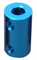
You can buy these from ebay but I reckon you have access to a lathe and some little bits of spare aluminium 2″ od bar right? I won’t teach you how to suck eggs here. Suffice it to say that I:
- removed the lead screws
- drilled (on the lathe) and tapped a 5mm thread in the end of the lead screws about 10mm deep. This is not actually very easy as the lead screws are made of some deceptively tough steel which is reassuring. Go easy with the drills, use Trefolex or some other cutting compound.
- Turned a bit of aluminium such that the lead screw fit into it and then screwed the handle on.
It is possible for you to use a mounted dremel to grind a flat on the stepper shaft but it’s frought with difficulty.
This leaves us with really only one option: a belt or gear system.
My initial idea was to cut a worm gear into the stepper coupler.
This can be done on a lathe using something like an 5mm tap etc. Then I could mount a small 5mm threaded shaft which drove the worm gear. The mounting would be tricky because it would have to be very free running in order not to hinder the general operation of the z-axis.
This is why I suggest 5mm for the worm gear because the delrin wheels we used earlier have a 5mm ID and I have some spare (so might you). Perhaps some sort of complex bearing system which used the stepper mounting hex standoffs for support?
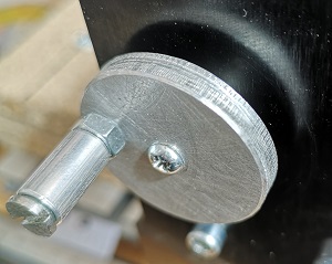
I wrestled with this worm gear idea quite a while before I eventually gave up on the idea. Instead I managed to lay my hands on a couple of small gear cogs (yeah Ebay), and did this :

And here is the y-axis jog wheel which would be identical to the x-axis wheel except that I ran out of aluminium rod so I used some PVC rod I had instead.
It’s still a little unsatisfactory because I cannot fit a ‘handle’, but it’s better than trying to get your thumb and forefinger in the gap beneath the stepper motor.
Sharpie holder
You’ll face the problem where you want to have a dry run at a job before you actually do it. You’ll do this initially by simply lifing the z axis above your job and seeing if it looks ‘kind of’ right. But you won’t know for sure until you actually begin the process.
What you need is a way of mounting a pen in exactly the same position (the centre) as the tool would be.
Spring mounting the pen will also make things much easier.
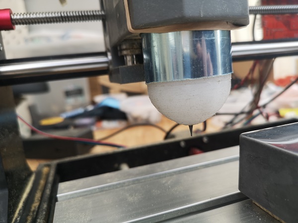
The easiest way to do this (well, if you have a lathe) is shown here (right click images and open in new tab to blow them up):

Mounting the pen like this (by removing the spindle) allows us to replace the pen with either the spindle itself or some other tool (drag cutter etc.) mounted the same way, and know that it’ll be in the same place. These sharpie pens are ubiquitous now. They cost next to nothing so I decided to make the holder specifically for them. You won’t need the springs, gravity will generally allow the pen to rise and fall correctly.
Far easier..
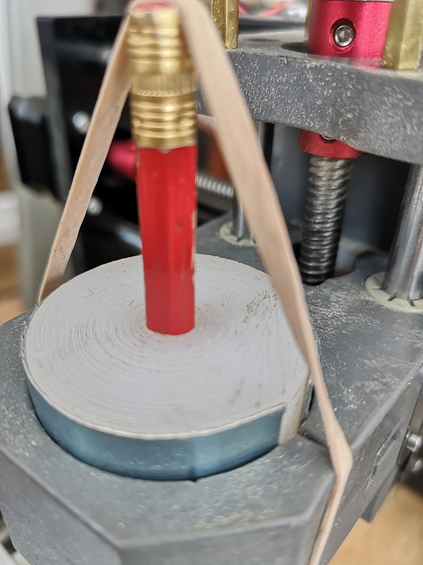
Of course, there is actually a far easier way to fit a temporary marker to the CNC3018. If you just want to quickly test the engraving GRBL you can use a pencil, sprung with an elastic band as shown below. This allows you to not worry too much about depth. The pressure of the pencil on the job will be maintained by the elastic band. Essentially we drill a hole in a cylinder, and partially block one end so the pencil butts against it but still protrudes.
Some insights
general maintenance
These machines do vibrate quite a lot, and one of the things that happens regularly is that the bearings will ride out of their moutings and fall down the shafts. Or The z-axis coupler grub screws will come loose, or some other bolts will come loose.
Get into the habit of tightening everything between long runs, or before you start a new job. Also consider using PTFE tape on some of the large bolts to help keep them in place.
You can use very fine machine or gun oil on the leadscrews and bearing shafts. You’ll find it reduces noise, and it will in the long run preserve the machine. But you will find that the oil collects dirt which is counter productive. Keep some super fine oil (not WD40, actual oil) near the machine. At the start of a job, apply a tiny amount to the screws and bearing shafts, and wipe everything down at the end of the job.
offline controller
I can’t stress this strongly enough YOU SHOULD buy the offline controller for the CNC 3018. This controller allows you to put files on a micro SD card and load them into the machine without needing a connected laptop.
The SD card is large and GRBL files are small, so you end up with a large library of GRBL files on the SD card, which you can cycle through using the offline controller menu system. If you have a jig that matches each job then you can quickly repeat any previous job without needing to mess around zeroing etc.
Using the gcodetools Inkscape plugin
Inkscape is a very good, free (as in beer) vector graphics tool which has a vibrant plugin community. One of the available plugins (extensions) is named gcodetools, written by a Russian guy.
This extension allows you to convert SVG ‘paths’ into GCode, but while it is fundamentally great it has some quirks.
One of those quirks is that the plugin by default does not return the z axis to its starting postition at the end of the run.
You can fix this by creating a file named ‘header’ and a file named ‘footer’ in the directory in which you are creating your grbl file.
I generally keep my SVG or 3d source files on the same SD card for ease of use, so I have a header and footer file on that sd card.
If you are drag engraving you can ensure the spindle does not start in the header by removing the spindle start command (M3 or M4) in your header file.
In the footer remember to add the comands :
G00 X0.0000 Y0.0000
G01 Z0.000000 F100.0 (return z to origin for possible second run)
This will return the spindle to it’s exact point of origin. You can now lower the z axis by a small amount and do a second run (if you wanted to).
A note on fonts and shading etc.
There are some other useful inkscape plugins. There is one named axidraw (sometimes also called eggbot) which allows you to take any text in any font and convert it into single paths for drag engraving. The same plugin can also be used to apply cross hatching inside shapes for the purpose of engraving.
Efcolor low temperature enamel
If you’re engraving you might also be considering filling that engraving with colour?
After much experimention I discovered efcolor low temperature enamel. It comes in powder form. You sprinkle it on the job and brush off the excess. Then you pop your job in the oven for 10 minutes, or above a t-lite candle and it sets hard like (well, something like) actual enamel.
It’s used a lot by the arts and crafts people for making jewelry etc.
Router Bits
The standard router bits that come with the cnc 3018 are worse than useless for anything except roughing out soft wood. They don’t cut their way through anything, rather they ‘murder’ their way through.
You should obviously choose the bits you use carefully. I’d recommend using standard 2 flute dremel bits on wood.
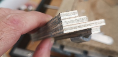
I did however find these on Aliexpress:
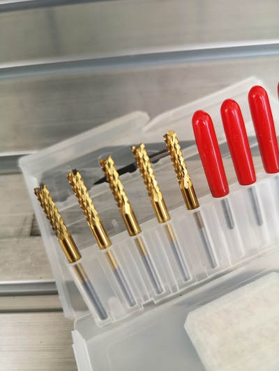
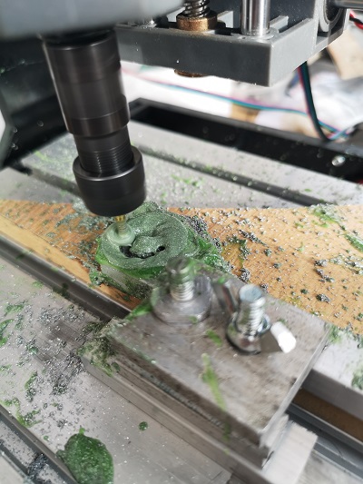
These are actually pretty amazing. I left the 3018 cutting the Dremel lathe arbor shown below. It was cutting a 10mm thick billet of Aluminium all day taking a tiny cut each pass (at speed ’50’ and 5000rpm. I expected to have to replace the cutter at least once, but when the job had finished the cutter was still in perfect condition. Still obviously super sharp to the touch (it’s the one on the left in the photo, it still looks perfect). They’re made of pure ‘unobtanium’. I strongly recommend you buy some for the tiny cost of a few quid.
Results
Ok you say: enough waffle! Did you do all that for nothing? Well firstly no.. I enjoyed every minute of it. It was the idea of robotics that got me into engineering in the first place.
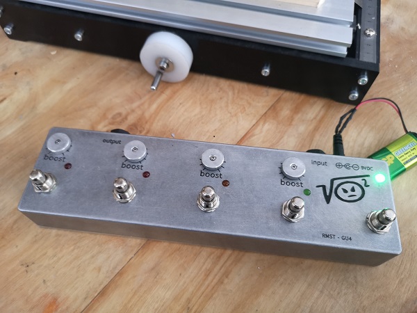
You can’t make a silk purse form a sows ear so obviously I’m not going to be ‘milling’ much with a CNC 3018 Pro. But I’ve managed to get the machine to do exactly the job I bought it for, which is to engrave lettering and logos onto the electrical enclosures I use for my guitar effects projects. The only part of the guitar effects process I couldn’t to myself before I bought the 3018.
Here are some examples of what I’ve managed to achieve with my machine.
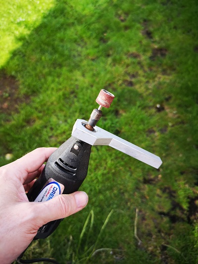
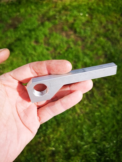
For those interested the Dremel thread (it being an American product) is 1/2″ 12 TPI. In the UK a 1/2″ BSF 12 TPI tap works perfectly in a 16.75mm hole. I did use a tap to cut the thread but I see no reason why I couldn’t have made a thread cutting tool and used the CNC to cut the thread. This, I will try sooner or later.
More to come..